
MRT Tunnel Monitoring in Very Soft Clay in Singapore
Monitoring a bored MRT tunnel through very soft clay requires more than collecting settlement readings. The real engineering task is to understand how ground deformation, groundwater response, tunnel construction and adjacent structures interact — and to identify when an unusual reading is a genuine geotechnical response rather than an instrumentation problem.
Why very soft clay changes the monitoring strategy
Where a bored MRT tunnel passes through very soft and highly compressible clay, relatively small changes around the excavation can produce measurable ground movements. Monitoring therefore needs to capture not only the magnitude of deformation, but also its depth, direction, rate, spatial distribution and relationship with groundwater and tunnelling activities.
Low ground stiffness
Soft clay can deform significantly under changes in total and effective stress. A monitoring system should therefore distinguish local tunnel-induced ground loss from broader ground movement.
Groundwater interaction
Changes in pore-water pressure may occur before, during or after tunnelling. Settlement data should therefore be interpreted together with piezometer monitoring rather than in isolation.
Delayed deformation
Ground response does not necessarily stop when the TBM has passed. Post-passage deformation may continue and should be evaluated against pore-pressure recovery, deep-ground movement and the construction timeline.
Representative Singapore tunnelling scenario
Consider a twin bored MRT tunnel advancing beneath a developed urban area. The alignment passes through a substantial thickness of very soft clay, while buildings, utilities, roads and other sensitive assets remain in service above the tunnel influence zone.
Primary monitoring objectives
The monitoring programme needs to establish whether tunnelling is producing unacceptable ground loss, groundwater disturbance, lateral deformation or movement of adjacent structures.
This normally requires an integrated instrumentation and monitoring approach rather than reliance on one instrument type.
Assets potentially affected
Depending on the alignment, monitoring may extend from the tunnel itself to ground surfaces, nearby buildings, underground utilities, retaining structures, roads and other infrastructure within the assessed influence zone.
Where adjacent structures are sensitive, building monitoring provides an additional layer of evidence.
Key instruments and what each one is responsible for
No single instrument can explain soft-ground tunnelling behaviour. Reliable interpretation comes from combining independent measurements that observe different parts of the same ground–tunnel–structure system.
| Monitoring Instrument | Primary Responsibility | What the Engineer Looks For |
|---|---|---|
| Ground Settlement Markers | Measure vertical movement at or near ground level and define the development of the settlement trough. | Settlement magnitude, rate, symmetry and movement relative to TBM position. See settlement monitoring. |
| Deep Settlement Points / Extensometers | Identify where vertical deformation is occurring below ground instead of measuring only the final surface response. | Concentrated deformation near tunnel level, progressive compression through clay layers and delayed movement. |
| Inclinometers | Measure lateral ground deformation with depth, particularly near shafts, retaining structures, transition zones or other critical interfaces. | Shape of the displacement profile, depth of movement and sudden changes in movement rate. See inclinometer monitoring. |
| Vibrating Wire or Standpipe Piezometers | Monitor groundwater level or pore-water pressure and help determine whether hydraulic changes are contributing to deformation. | Pressure reduction, abnormal pressure increase, recovery after tunnel passage and correlation with settlement. See piezometer monitoring. |
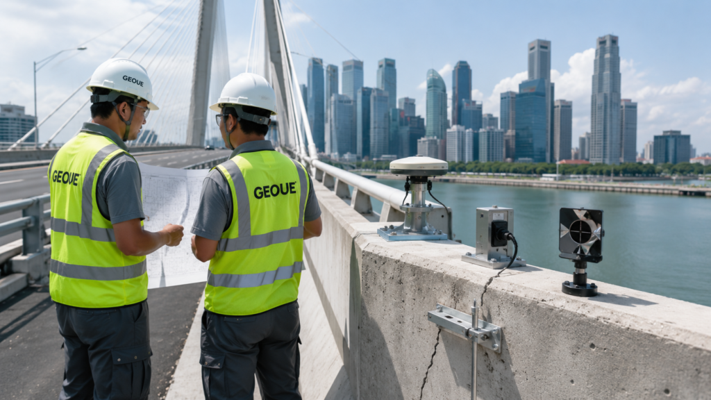
| Survey Prisms / Automated Total Station | Measure three-dimensional movement of buildings, structures, tunnel elements and other selected assets. | Vertical and lateral displacement, movement direction and spatial correlation between multiple targets. See survey monitoring. |
| Building Settlement Points | Detect differential and absolute settlement of adjacent buildings. | Differential movement between columns, corners or structural zones rather than ground movement alone. |
| Tiltmeters | Detect changes in structural inclination where differential movement may affect sensitive buildings or structural components. | Progressive rotation, change in movement direction and correlation with settlement measurements. |
| Crack Meters | Quantify opening or closing of selected existing cracks in adjacent structures. | Whether crack behaviour correlates with tunnelling-induced movement or appears independent. See crack monitoring. |
| Tunnel Lining Survey Targets | Monitor movement, convergence or distortion of completed tunnel lining where required by the monitoring design. | Relative movement between monitoring sections, persistent convergence and changes after ring installation. |
| Vibration Monitors | Record vibration at sensitive structures where construction activities or surrounding works warrant vibration assessment. | Event-specific peaks and whether they correlate with the tunnelling operation or unrelated site activities. See vibration monitoring. |
The monitoring instruments are only half of the story
A strong tunnelling monitoring review should correlate instrumentation readings with the actual construction sequence. A settlement value without knowing where the TBM was at the same time provides only part of the evidence.
TBM position
Compare movement against the distance between the monitoring point and the tunnel face, shield and tail.
Operational parameters
Face pressure, advance rate, thrust, torque and other available operational information provide essential context for interpreting unusual ground response.
Grouting information
Tail-void grouting records should be reviewed when settlement accelerates during or shortly after shield passage.
This is one reason why automated monitoring can be valuable in critical areas: higher-frequency data make it easier to compare the timing of movement with tunnelling events.
Common abnormal monitoring situations and how to interpret them
An abnormal reading is not automatically an abnormal ground condition. Before an engineering conclusion is made, the reading should be validated against neighbouring instruments, previous trends, construction activity and the physical condition of the monitoring point.
One settlement marker suddenly drops while nearby points remain stable
An isolated jump should first trigger data validation rather than an immediate assumption of widespread ground movement. Possible causes include disturbance of the marker, survey reference problems, accidental impact or an erroneous observation.
Engineering check: repeat the observation, inspect the point, check reference stability and compare against nearby ground and structural monitoring points.
A coherent settlement trough develops as the TBM approaches and passes
When several settlement points respond in a spatially consistent pattern linked to TBM progression, the evidence is much more likely to represent genuine ground response.
The important question is not simply whether settlement has occurred, but whether the magnitude and rate remain consistent with the project prediction and response framework.
Settlement continues after the tunnel face has passed
In very soft clay, deformation can continue after face passage. Interpretation should consider deep-ground settlement, groundwater response, tail-void behaviour and whether the rate is stabilising, constant or accelerating.
Persistent post-passage movement deserves greater attention when it is supported by multiple independent instrument types rather than one point alone.
Pore-water pressure falls and settlement accelerates at the same location
A correlated reduction in pore-water pressure and increase in settlement may indicate a hydraulic component to the observed ground response. Potential causes should be investigated against groundwater-control activities, possible leakage pathways, tunnelling records and instrument condition.
This combination is generally more significant than either trend considered independently.
A piezometer shows a sudden pressure increase during tunnelling
A pressure rise does not automatically indicate failure. It may be associated with temporary stress changes, pressurised tunnelling or grouting activities, but sensor behaviour and construction timing must be checked before assigning a cause.
An inclinometer develops a sharp localised change at one depth
A repeatable change concentrated at a particular elevation may indicate localised ground deformation, but casing damage, probe positioning, groove condition and reading repeatability should also be checked.
The full displacement profile is generally more informative than looking only at the maximum lateral displacement value.
A building prism moves but nearby ground points do not
Possible explanations include local structural response, movement of the target itself, survey geometry or reference issues. Building tilt, settlement points and crack monitoring can help determine whether the movement represents a genuine structural response.
A sensor becomes perfectly flat during an active construction period
A flat line should not automatically be interpreted as stability. Power failure, logger interruption, communication loss, sensor saturation, cable damage or frozen data may create apparently stable readings.
Correlation is more important than any single reading
The strongest evidence usually comes from several independent observations telling the same engineering story.
Example of stronger evidence
Surface settlement increases, deep settlement shows deformation near tunnel level, nearby building prisms move in the same period and piezometers show a corresponding hydraulic response.
The combined evidence is considerably more meaningful than one settlement marker exceeding its previous trend.
Example of weaker evidence
One survey point changes abruptly, every neighbouring point remains stable, the TBM is remote from the location and a repeat observation returns close to the original value.
This pattern points first toward validation of the measurement system.
A practical abnormal-reading review sequence
GEOUE recommends treating every significant abnormal reading as an engineering investigation rather than a single-number decision.
For independent interpretation of complex or conflicting data, monitoring review and geotechnical monitoring consultancy can provide an additional technical layer between raw measurements and project decisions.
Good interpretation starts before tunnelling begins
One of the most common weaknesses in monitoring is focusing on construction readings without first establishing a reliable baseline.
Pre-construction baseline
Baseline readings should establish the normal behaviour, repeatability and stability of each instrument before it becomes affected by the works.
Ground model
Monitoring interpretation should be connected to the geotechnical profile. Appropriate soil investigation provides the stratigraphic and groundwater context needed to understand why different instruments respond differently.
Do not isolate the bored tunnel from shafts and temporary works
Launch shafts, retrieval shafts, station boxes and other temporary works can influence the same ground and groundwater system as the bored tunnel. Monitoring interpretation should therefore distinguish TBM-related behaviour from deformation caused by excavation, retaining systems or groundwater control.
Where an alignment interacts with major excavation works, ERSS monitoring and deep excavation monitoring should be reviewed together with the tunnelling dataset.
The GEOUE approach to tunnel monitoring
GEOUE approaches geotechnical monitoring as an integrated engineering information system rather than a collection of isolated instruments.
Instrument selection, installation quality, baseline establishment, monitoring frequency, automated acquisition, data validation, cross-instrument correlation and engineering interpretation all contribute to the reliability of the final monitoring conclusion.
For Singapore infrastructure projects, GEOUE supports geotechnical instrumentation, monitoring strategy, technical review and related engineering services for tunnelling, excavation, buildings and other construction environments.
Key lessons from very soft clay tunnelling
Do not rely on one instrument
Settlement, pore pressure, lateral movement and structural response answer different engineering questions.
Rate matters
A change in movement rate or acceleration may provide more useful information than the absolute reading alone.
Location matters
Every monitoring trend should be interpreted against TBM position, geology and the surrounding construction sequence.
Groundwater matters
In compressible fine-grained ground, hydraulic behaviour can be inseparable from deformation behaviour.
Validate anomalies
An abnormal reading should be confirmed before an engineering cause is assigned, while genuine correlated movement should be escalated promptly.
Continue after passage
Monitoring should continue for the period required by the project because soft-ground response may persist after the tunnel face has passed.
Engineering note
Monitoring thresholds, frequencies, action levels and response measures are project-specific. This case study intentionally does not provide generic numerical Alert, Alarm or Work Suspension values because these should be defined by the approved project design, specifications and responsible engineering professionals.
Planning a tunnelling monitoring programme in Singapore?
GEOUE supports instrumentation planning, monitoring implementation, data interpretation and technical review for soft-ground tunnelling, underground construction and adjacent asset protection.
Contact GEOUEOur Engineering Services
End-to-end instrumentation and monitoring solutions for safe, efficient and data-driven projects.

Instrumentation & Monitoring
Design. supply and installation of geo / structural instruments.

Soil Investigation
In-situ and lab testing
to assess ground conditions.
Geophysical Survey
Advanced geophysical methods
for underground mapping.

Geotechnical Consultancy
Technical advisory and design support for geotechnical works.

Survey
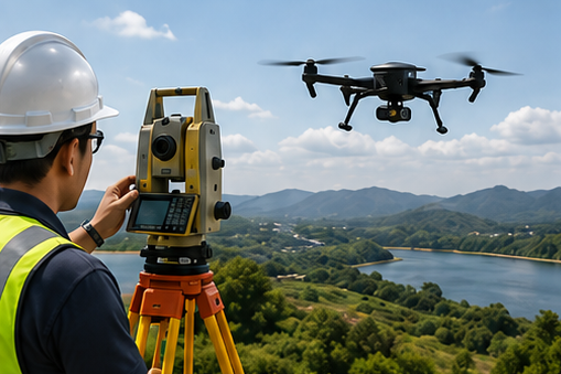
Precision surveying using total stations, GNSS, LiDAR and drones.
Structural Monitoring
Real-time monitoring of structures for performance and safety assurance.

Installation
Professional installation by experienced teams with strict quality control.

Maintenance
Routine maintenance, and data validation for long-term performance.
Singapore Project Experience
The GEOUE team members have participated in a wide range of geotechnical instrumentation and monitoring projects across Singapore, including transportation infrastructure, deep excavation, underground construction and private developments.

MRT & Rail Projects
Instrumentation and monitoring works for MRT lines and rail infrastructure.

Deep Excavation
Monitoring of deep basements and retaining structures in dense urban areas.
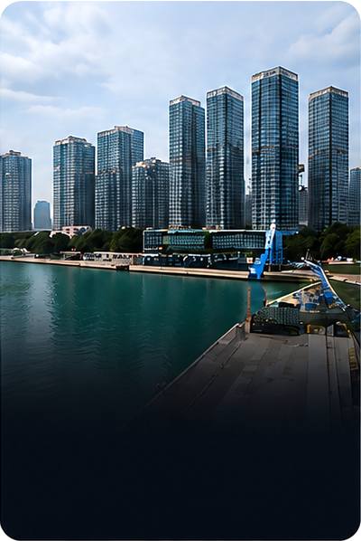
Building & Development
Monitoring solutions for high-rise, mixed-use and residential developments.
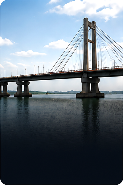
Bridges & Structures
Structural health and performance monitoring for bridges and infrastructure.
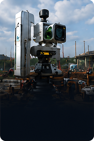
Industrial & Utilities
Instrumentation and Monitoring for utilities, tunnels, pipelines and industrial facilities.
Our Approach

Understand
We study your site and project requirements.

Monitor
We monitor, analyze and
provide actionable insights.

Design
We design the right
solution for your needs.

Partner
We partner with you to
ensure long-term success.

Deliver
We install and commission
with precision.

Support
We maintain and support
for the long term.
Our Core Services
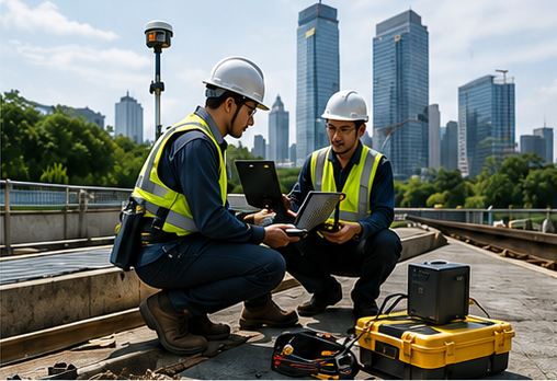
Instrumentation & Monitoring
Real-time data acquisition and monitoring for geotechnical and structural applications.
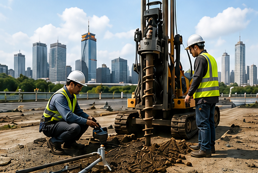
Soil Investigation
In-situ tests, sampling and laboratory analysis to evaluate subsurface conditions.
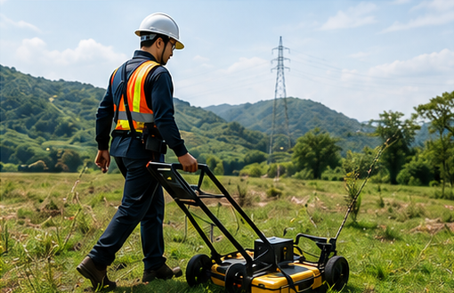
Geophysical Survey
Advanced geophysical methods to map subsurface conditions non-destructively.
Geotechnical Consultancy
Design optimization and risk-based advice for safe and cost-effective solutions.

Monitoring Data Analysis
Trend Review
Alert Assessment
Interpretation
Technical Review
Third-party Review
QA/QC
Independent Assessment
Get In Touch
Let’s Work Together on Your Next Project
We deliver engineering solutions that make a difference.